


The LS14008 Cole Hersee isolation switch is designed for high-current applications in mining, transport, and industrial operations. Proper installation is critical to ensuring safety, compliance, and reliable performance. Incorrect installation risks overheating, arcing, or damage to downstream equipment.
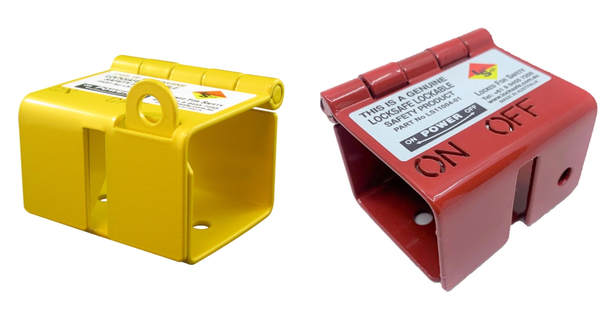
This guide provides a detailed breakdown of each stage in the process, from preparation to commissioning. Each step is supported with clear instructions and technical considerations, ensuring installers follow correct procedures. For additional accessories such as lockout devices, refer to our products for compatible equipment.
Key Specifications and Requirements
Before beginning installation, it is essential to understand the switch’s operating limits and design.
- Current ratings: 2000 A intermittent, 300 A continuous
- Mounting: 19 mm hole, dimensions 75 mm × 125 mm
- Weight: 0.55 kg
- Terminals: two 12.5 mm main, two 4.5 mm field
- Protection: O-ring sealed housing
Knowing these details ensures the LS14008 is installed in an appropriate location with the correct conductor sizes and hardware. Verifying specifications reduces the risk of mismatched connections or premature wear.
Tools and Preparation
Proper preparation prevents delays and safety risks. Installers should gather both tools and safety equipment in advance.
Steps to prepare:
- Gather tools: torque wrench, drill, screwdrivers, ratchet set, and cable lugs matched to conductor size.
- Prepare safety gear: insulated gloves, safety glasses, and lockout tagout devices.
- Isolate the power supply. Use a meter to verify the system is de-energised.
- Apply lockout devices and tags to prevent accidental energisation.
- Mark mounting holes using the switch footprint, then drill and deburr to ensure clean edges.
Each of these steps reduces the likelihood of faults. For example, deburring prevents conductor insulation damage, while proper lockout ensures no current flows during work.
Mounting the Switch
The switch must be mounted securely to maintain weather resistance and mechanical integrity.
Steps to mount:
- Position the switch so the O-ring seal sits flush against the mounting surface.
- Install bolts, washers, and nuts evenly to avoid housing distortion.
- Tighten bolts to the specified torque, avoiding overtightening.
- Confirm clearance so the rotary handle turns freely.
- Check accessibility for future inspections and servicing.
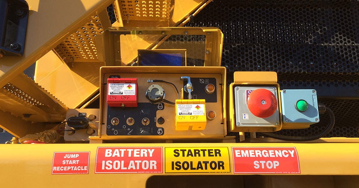
Each mounting step supports long-term reliability. For example, uneven bolt tightening can compromise the O-ring seal, allowing dust or moisture inside. Positioning the switch in a visible and accessible location ensures operators can isolate circuits safely during maintenance.
Wiring and Electrical Connections
Electrical connections must be completed with precision to prevent overheating and poor conductivity.
Steps to wire:
- Prepare conductors with crimped lugs suited to the 12.5 mm and 4.5 mm terminals.
- Attach main conductors to the larger terminals and field wires to the smaller ones.
- Route cables neatly without bends that place stress on insulation.
- Install insulating boots on exposed terminals for additional protection.
- Torque all terminal bolts according to manufacturer specifications.
- Test insulation resistance with a meter to confirm no faults.
Proper lug sizing is critical to avoid loose connections that generate heat under load. Using insulating boots reduces exposure to dust and moisture, improving long-term durability. Final resistance tests confirm that no current leakage exists before commissioning.
Testing and Commissioning
Final testing ensures the LS14008 is operating as intended before re-energising the system.
Steps to commission:
- Conduct continuity tests in both on and off positions while de-energised.
- Verify that downstream loads remain disconnected in the isolated state.
- Restore power and cycle the switch under load.
- Fit identification labels and isolation tags in line with site standards.
- Record commissioning
Each step provides assurance of compliance. Continuity checks confirm the mechanical and electrical function, while initial load cycling ensures the switch performs under operating conditions. Labelling and record-keeping meet WHS requirements and assist future maintenance teams.
Brand Support and Assistance
The LS14008 is designed for safe isolation in demanding environments, but correct installation and servicing are essential.
At Locksafe, we supply the LS14008 alongside a wide range of electrical isolation solutions. Our support includes technical guidance, safety advice, and access to replacement components.
For installation assistance or additional equipment, contact us directly. Our team ensures that all products meet Australian safety requirements and are suitable for heavy-duty use in mining, industrial, and transport sites.


